Several years ago I needed to replace the ballast for the compact fluorescent bulb on a 13 gallon Nano Cube aquarium. Looking around for replacement ballasts I discovered that they were quite expensive. I had the idea to try to use the ballast from one of those screw-in fluorescent bulbs. Well, It worked and since then, I have used this same process to power other compact and normal fluorescent bulbs.
First, you need to find a screw-in fluorescent bulb that puts out a similar wattage as your bulb. I have found that as long as you are within a couple of watts you are OK. You can even overdrive your bulb a bit. By overdrive I mean using a ballast that puts out a higher wattage than your bulb is rated for. This will put out more light at the expense of shorter bulb life. Overdrive at your own risk! You are working with electricity so follow these directions at your own risk and please, be safe!
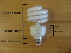
The ballast is located in the plastic base. To get to it, you need to separate the top of the base from the bottom. The easiest way to do this is to use a Dremel tool with a cutting wheel to cut around the base at the seam between the top and bottom. If you do not have a Dremel tool, you can use a hacksaw and screwdriver. Use the hacksaw to just barely cut through the seam in 3 places then use a flat head screwdriver to pry the top of the base off. Try not to break the glass bulb and remember to dispose of it properly because it may contain mercury and other toxic chemicals.
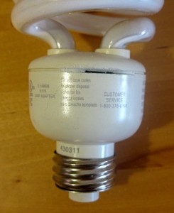
There will be two wires connecting each end of the glass bulb to the ballast. These will need to be cut.
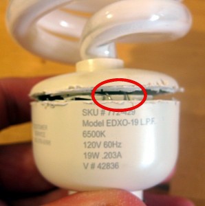
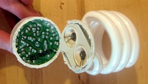
If you are lucky, you will be able to pull the ballast out of the base at this point. If you bulb is like the one pictured, the ballast is upside down and you may need to make some additional cuts. Use a Dremel with a cutting wheel or hacksaw to cut around the base just above the metal screw-in part.
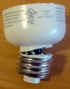
There will be 2 wires connecting the metal screw-in part to the ballast. You will need to cut these to free the ballast.
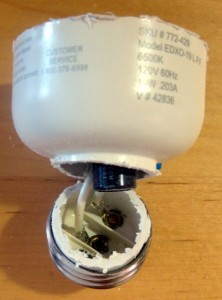
Now you will be able to push/pull the ballast out of the plastic base. The hardest part is over. You will need to solder 6 new wires onto the ballast; 2 for power, and 4 that will connect to your bulb. If you are replacing a ballast, you can use the wires from the old ballast. If you are using this ballast in a new installation, you will need 4 wires to connect the ballast to your bulb/bulb holder and you will need a new power cord. I usually use a cheap extension cord for power. Cut off the female end, strip the two wires and solder them to the ballast where the wires connecting the metal screw-in part used to be.
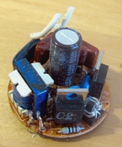
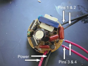
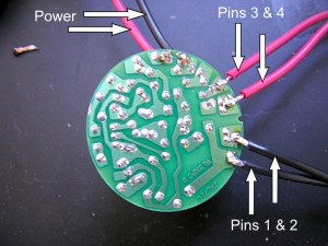
Most common fluorescent and compact fluorescent bulbs have 4 pins. You will need 4 wires connecting the ballast to each pin. Many of these ballasts have pin numbers labeled and some bulb/bulb holders have pin numbers labeled. If not, you can use trial and error to find the correct configuration. Usually pins 1 & 2 are next to each other and pins 3 & 4 are next to each other, but it can vary.
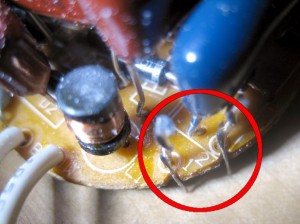
If you are using a metal bulb reflector you will want to use a 3 pronged, grounded power cord and connect the ground wire to the metal reflector. Be sure you are connecting the ground to the reflector and not connecting one of the hot wires to the reflector. Position the ballast where it is protected from people, water, and metal. Hot glue, Velcro, and epoxy work well to secure the ballast inside a hood.
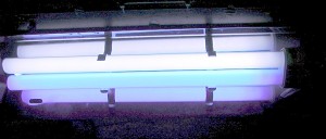
I have used these ballasts to power T12, T8, T9 (circline bulbs), and various compact fluorescent bulbs. I suspect that they will work with T5 bulbs, but I do not know for sure. I doubt they will work with high output bulbs (HO), very high output bulbs (VHO), or bulbs with only 2 pins, but again, I do not know for sure. Good luck!

Wow! Worked just as shown. I have a circuline t9 and the ballast bought from Home Depot didn’t work. So I looked around the house and found a 20w CFL (the T9 is 22w) then followed the directions shown here and, voila, light! Thanks.
dear makify can you please make a 40 inch longboard template